 Kawasaki Z1 , The Headstream and its Path , Development of the N600 / T103
(By Gyoichi Inamura)
(Translation Japanese to English by Z1Achim)
(Pages from the book: 47/48/49/50/51/52/53/73/75)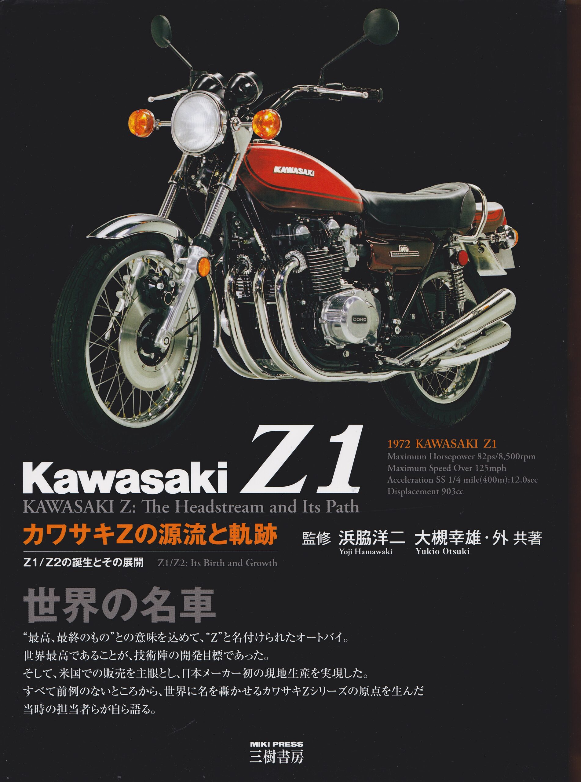
Prototypes N600
Prototypes T-103
When Kawasaki acquired Meguro Motors, they believed the 2-stroke world had no future. Therefore, I gathered information from the British magazine "MotorCycle," the American "SAE Journal, " the German magazine "ATZ" (Automobile Technical Journal), and other magazines that were then in the Akashi factory library.
We also bought used engines that looked usable, disassembled them, measured their dimensions, drew them, and collected and organized various data. During the maintenance work for the mass production of these engines, we summarized the data from inside and outside the company in this way in charts, etc., so that later, when the sales department requested them, the basic specifications could be easily determined. Until then, the development staff for four-stroke engines all came from the design and testing departments, including Mr. Suekoichi, Mr. Yamada Tadashige and Mr. Inoue Takashi. I was part of a small group of employees consisting of Mr. Hashimoto, Mr. Toshihiko Suzuki, and two other employees, Mr. Horii and Mr. Rikiya Chatani. None of us had experience in mass production of motorcycles. In April 1967, we received our first small development budget. However, we were unsure of which engine to design, so we decided to wait until we had confirmed the performance and durability of the developed engine to begin work on the chassis. At that time, Mr. Otsuki headed the entire engine design team, including two-stroke and four-stroke engines and the transmission department, and I was appointed head of the four-stroke engine department. My new group included Tadashige Yamada, Toshihiko Suzuki, Takashi Inoue, and two or three other outside artists. The specifications at that time were a four-cylinder DOHC engine with 750cc (64 mm x 58 mm), and the internal development code was N600. I wondered how my immediate supervisor, Mr. Otsuki, felt about implementing this plan when I brought him the drawings.I knew from documents that Honda had used a motorcycle with similar specifications in a race car in Japan, and that MV-Agusta produced a small number of shaft-driven vehicles in Italy.
However, I didn't know the details of the internal workings. I wanted to see the original, so I searched for these motorcycles in Japan, but couldn't find one. I called an importer, but he couldn't help either. Despite all this, our plan progressed steadily, and I believe it was toward the end of the N600 prototype that we actually got our hands on an MV Agusta engine. Although we were eventually able to obtain it, we realized it wasn't suitable for the production car we were aiming for. Therefore, we only made sketches and finished work on that model. It was a difficult project, and we were complete novices. So, it would have been understandable if it had been a test series, but for a production car, we couldn't easily create such a drawing. Department head Mr. Otsuki believed the proposal would be accepted by the Kawasaki board, saying, "A 4-cylinder DOHC would be good, but we have to make it the best in the world." The only other thing we were asked to do was make the crankshaft sufficiently strong. Based on my previous experience, I considered what performance and characteristics the N600's engine should have. I laid out my basic ideas and decided on the engine specifications.This was a very enjoyable phase of the design, and there was no one to criticize me or anyone around me.
So I felt free, but at the same time, I felt the burden of responsibility. I emphasized the following five points regarding the N600 :
- It had to have world-class power—74–75 hp, which corresponds to Mr. Otsuki's initial impression of "Best in the World."
The goal was to be the best in the world. I also thought we had to consider that the engine could also be used in racing, depending on the circumstances. - Measures to minimize wear. I was concerned about the cause of the W2-SS's stiffness and vibration problems, so I opted for a 4-cylinder engine. Kawasaki was having some success with the H1 two-stroke 3-cylinder, and Triumph with the BSA 750cc three-cylinder Rocket 3 in Great Britain. However, when I tried to work on the W1, I found that the vibrations couldn't be eliminated sufficiently theoretically. I also couldn't accept the idea of a differential due to its simplicity. The asymmetry of the three-cylinder engine seemed strange to me from an aesthetic point of view. I wanted to avoid making the three-cylinder engine wider than the rider's handlebars. So I opted for an inline four-cylinder. There are two types of engines that are positioned in the direction of travel and those that are positioned perpendicular to the direction of travel. Under heavy loads, there was a concern that the torque movement would compromise control. Since the latter was chosen, the inline four-cylinder was adopted.
- The inline four-cylinder engine has the potential for improved performance. To ensure the high-speed performance potential of a four-stroke engine, it was considered necessary to lighten the valvetrain and ensure system rigidity, regardless of whether the intake volume or the engine speed was increased. For this reason, a DOHC with direct valvetrain was chosen. (Although it was expected to be more expensive, the cylinder head structure would be simpler than the OHC that would be used in the future.)
- The inline four-cylinder engine offers perfect durability and reliability. If these requirements were not met, Kawasaki would not enjoy market credibility, regardless of the four-stroke motorcycles it launched in the future. This was therefore a matter of utmost importance. The camshaft bearings at the shaft end were removed to prevent the rider's kneecap from contacting the cylinder head cover at the end of the intake camshaft. To ensure shaft rigidity, the camshaft was constructed from a chromium-molybdenum shaft with high rigidity (high elastic modulus) and white metal with good bearing properties, instead of cast iron with good bearing properties. 5) Adaptation to manufacturing and service capacities. Costs were neglected for the crankshaft and its bearings, and a robust, assembled crankshaft with six main bearings and roller bearings for the connecting rod bearings mounted directly on the crankpin was used. Since the ability to maintain sufficient cleanliness in the workshops could not yet be expected, roller bearings were used, which are less sensitive to dirt and foreign matter than when using plain bearings. At that time, assembled plain-bearing crankshafts did not require large investments in workshop equipment. During this phase, the product planning team created a so-called development plan, which defined the objectives of the developed model, market stability, cost targets, production volume, development budget, etc. However, there was no such department at the time, and the development engineers created plans and specifications themselves. From that point on, I was in constant contact with the department head, Mr. Otsuki, and worked on the drawing. First, we discussed the construction of the crankshaft. The crankshaft is the backbone of the engine and of utmost importance. If it gets stuck, the engine is hopelessly lost. I wholeheartedly agreed.
The N600 test engine was completed in March 1968 and tested on the dynamometer. However, there was neither a dedicated test facility nor a test vehicle. So we began by constructing a frame to mount the engine to the dynamometer and had to get designers and testers to work together. The head of the technical department instructed that the engine should not be mounted on the chassis until it was running normally and producing 70 to 75 hp. So the testing began. We chose a displacement of 750cc because most British sports bikes at the time were 750cc. However, the N600 was a 4-cylinder DOHC, and we thought it could compete in terms of power.
At the beginning of the performance tests, we were already able to ensure high power (over 70 hp / 1 liter displacement), but during the durability tests on the dyno, the following two problems arose, which we found difficult to solve.
First: Gas and oil leaks from the cylinder head gasket. This was due to the fact that we were unable to achieve wind protection equivalent to the cooling airflow at cruising speed, and also because the gasket itself was performing poorly. Its primary function was to prevent leakage caused by excessive heat and surface pressure. The reason for the excessive surface pressure was that the gasket was secured between the aluminum cylinder with the pressurized cast iron liner and the cast aluminum cylinder head with a steel bolt anchored in the crankcase. During sustained high-performance operation, the gasket was so worn due to the different thermal expansion of the two materials that it could no longer be repaired. During operation, neither gas nor oil leaks occurred, but after stopping and restarting the engine, the gasket's sealing capability was compromised. To solve this problem, we planned to use a material with better surface pressure recovery for the seal in the next prototype, increase the mating surface to reduce the surface pressure, adjust the washer to achieve uniform surface pressure, and seal the cam chain tunnel with a heat-resistant silicone rubber ring.
Second: Damage to the tappet shim (valve shim). This was due to the shim material itself being cut from bar stock rather than sheet material. The fiber flow process of the shim material caused the grains to stretch in a direction perpendicular to the grain growth direction, making the material more prone to stretching than suitable for its intended use. There were many other problems, but performance and durability were promising, and development was nearing completion when Honda announced the CB750, a four-stroke, four-cylinder SOHC with a single front brake, at the Tokyo Motor Show in October 1968. This was a major shock for Kawasaki, but it didn't seem to be the best course of action to continue with the current plan. So, the problems were addressed with the prototypes in progress.
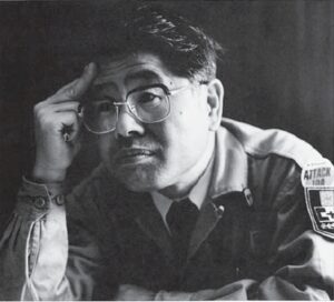
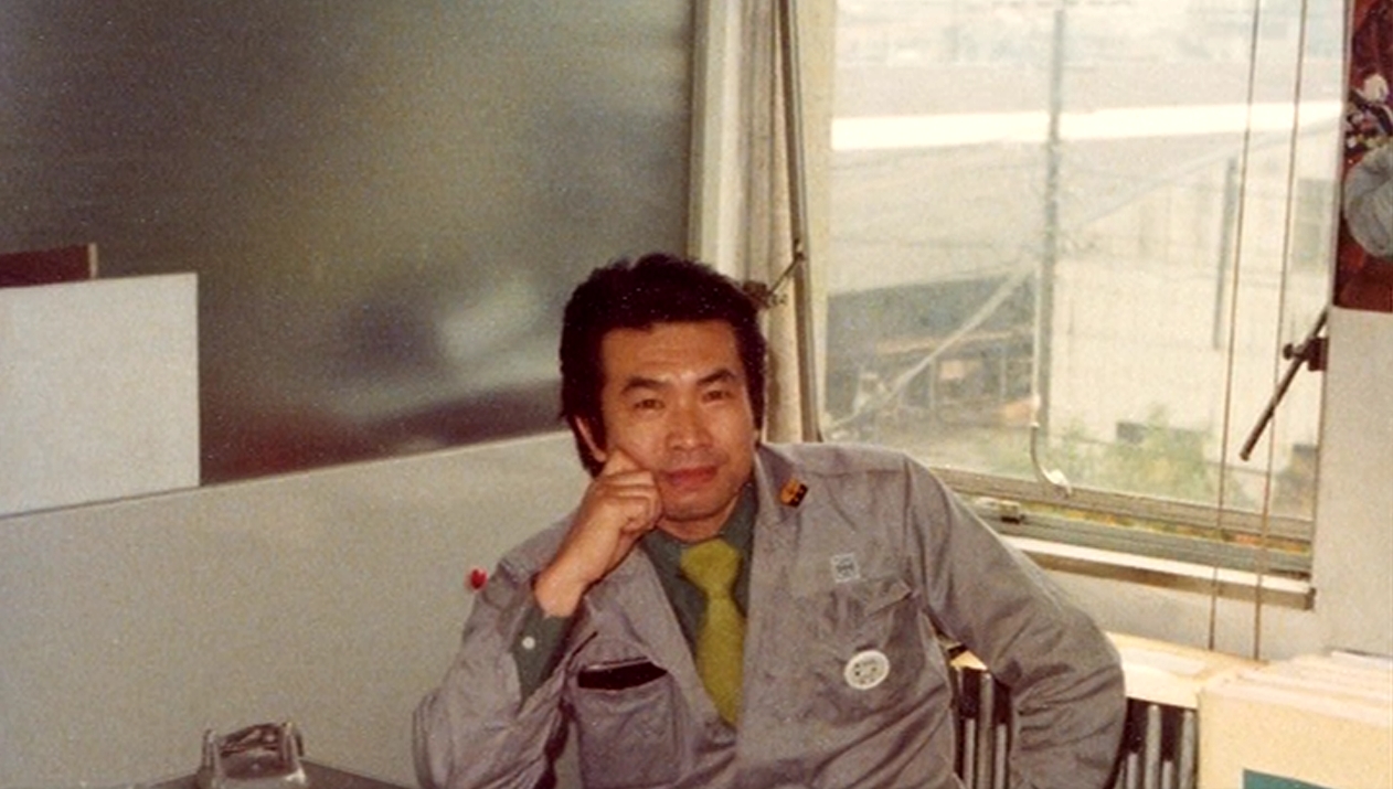
Gyoichi INAMURA
The author (Gyoichi INAMURA) has worked on many Kawasaki 4-stroke engines and developed the 400 cc 2-cylinder engine, the 650 cc 4-cylinder engine, and the 750 cc 2-cylinder engine.
The problems were solved, but instead of selling the engines, Kawasaki Heavy Industries, Japan, and KMC (Kawasaki Motor Corporation; USA) decided to work together to reconsider future plans.
In August 1969, Kawasaki's department manager, Mr. Yamada, and department manager, Mr. Otsuki, visited KMC in the USA.
KMC's department manager, Mr. Hamawaki, vice president, Alan Macek, and the heads of each department, Mr. Tanegashima and Mr. Ido, who were responsible for product planning, also met to discuss the current status of the N600 prototype and the future direction of the larger models. Regarding the technical aspects, KMC made various suggestions, and the discussion continued, with me primarily responding to questions from the Chief of Staff via email. The following conclusions emerged: 1) If the N600 currently under development at Kawasaki remains as it is, there will be no problems, as the concept, although it has differences in detailed design, is the same. 2) Since Honda has released a large 750cc 4-cylinder model, this trend is expected to continue in the future, considering that there are still large American and British vehicles. 3) Based on its current success, it was decided that the next model to be developed after the N600 should be a large model, no larger or heavier than the Honda model, and that the details should be left to Kawasaki's engineers in Akashi. Based on this result, department head Mr. Otsuki drew up a development plan outlining the basic ideas. This was in November 1969.
The T-103 Prototype This model's displacement was approximately 900 cc or more, it was an inline four-cylinder with variable camshaft control, and the development code was changed from N600 to T-103. With the T-103, it was important to increase the displacement to approximately 1200 cc by boring it out, as it was intended to compete with Honda. In February 1970, as production of the N600 reached its final stages, Don Grapes, the head of sales for KMC USA, came to Japan and attended the testing at the Motorcycle Research Institute in Yatabe, Ibaraki Prefecture. As expected from the head of the local sales department, his riding skills were impressive, and he seemed pleased with the performance.
He not only rode the motorcycles, but also watched us disassemble and service them, and gave us some very strict comments. The biggest problem was that with such a large engine, even the most experienced American dealer would have had difficulty removing it from the vehicle to inspect and repair it. So we first had to check whether the cylinder head cover could be removed and the valve clearance adjusted while the engine was still mounted in the vehicle, whether the cylinder and pistons could be removed, etc. These points were easy for us to understand, and we therefore carefully considered them for the next production prototype of the T103.
Development of the T-103: A new design was initiated, incorporating the results of the development and testing of the N600. This model was given the aforementioned development codename T103, which would become the model for the future N600. The main engine was a 4-cylinder DOHC engine with a bore x stroke of 66 x 66 mm, a wet multi-plate clutch, and a 5-speed J-type gearbox. The width of the engine was the most important consideration in the design, as a parallel engine is mounted horizontally and the driver sits astride it.
Therefore, the bore x stroke was squared and the exhaust was set at 100 cc, which reminds me of my favorite Harley-Davidson Sportster. Later, voluntary restrictions were introduced by the four Japanese manufacturers, but ultimately, they were not subject to self-regulation. This T-103 prototype was the second prototype and also what we call the mass-production prototype. Since this was our first time producing a 903 cc model, we used the mass-production prototype molds to manufacture the prototype. We also made a sand mold on the same surface to quickly produce a prototype that could be produced faster than with a mold, and we tested the parts in detail. We completed the prototype at the end of 1970. From then on, testing for the Z1 went smoothly, and we had the opportunity to familiarize ourselves with the American market. Mr. Tanegashima Tsune, who had worked with me on product planning for the Z1 from the beginning, and Tada Ken, who was responsible for the design. I met with Alan Masek from KMC at the café. The main purpose was to show KMC the final Z1 model and hear their opinion. We also wanted to conduct market research with Mr. Tanegashima on how we should proceed with product planning after the Z1. As a result, we decided that the next model to be developed after the Z1 would be a 650 cc four-stroke, four-cylinder model, a Z1 Junior, and a 600 cc multi-purpose model in parallel. Incidentally, at that time, the four-stroke engine development group was focusing all its efforts on developing the Z1, so freelancers were assigned to work on that model. However, the 600 cc single-cylinder engine was technically very difficult, and while we struggled, the sales department showed little interest, and development was halted after only one prototype. After returning to Japan, we worked hard to complete the Z1 at Ichigata Senri. Kawasaki was the first to produce such a four-stroke engine. We didn't know where to find specialized parts. So we formed a team and, to put it bluntly, searched all over Japan for suitable parts. With company Ozi, we were able to start working with a parts manufacturer that was on par with our competitors. This broadened our horizons and opened up new perspectives for both design and production. Production of the T-103 would normally begin with sand casting, as its displacement differed significantly from the N600. However, since we had already experienced the fundamental problems of the N600, we skipped this step and prepared the molds, tools, and equipment for mass production. We then manufactured a prototype. Serial production was completed in December 1971.
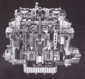
Development shifted from the N600 engine (750 cc class), which achieved over 70 hp in performance tests relatively early on, to the T-103 in the 900 cc class. The high-performance Z1 engine was born.
From now on, we will conduct a series of tests according to a checklist. However, unlike previous small-scale tests, we have encountered some new problems.
- Seizure of he connecting rod bearing. During disassembly, we discovered that the seizure was progressing from the connecting rod base. The axial force was pushing the connecting rod against the crank web, tearing the oil film and causing the seizure. Previously, we had assumed that, given the high machining precision of the components of this assembled crankshaft, no significant axial force would be generated. However, the assumption that the journals and the crankshaft centerline of the nine-part crankshaft would be parallel was a mistake from the outset, and we needed to find a way to avoid certain precision errors. It was common practice for other manufacturers products to have assembled crankshafts with up to two cylinders without thrust washers on the connecting rod. However, problems arose, and we wondered whether we should ask the manufacturer to improve the machining accuracy of the parts or solve the problem by adding shims, even if this would be more expensive. However, we were concerned about whether we could maintain the machining accuracy, which would not generate thrust, in future mass production. We also feared that adding even a small part with poor accuracy and the associated harsh operating conditions would result in seizure, causing inconvenience for everyone involved. Therefore, we had no choice but to insert thick washers. What kind of mechanism could prevent the washer from seizing ? Firstly, inserting a washer would reduce the relative sliding speed of the connecting rod and crank web.
Second, in the case of localized seizure, the resistance of the washer side would separate it from the other side, and the peripheral speed of the seized side would become zero, thereby suppressing heat generation. We assumed this would prevent snowball seizure.
The problem was solved by shortening the connecting rod and crank web to make room for the washers. Side washers were then added to both sides of the connecting rod. Even then, thrust would still be generated due to the differences in the crank radius within the machining tolerance. Therefore, the crank radius dimensions on the pin and web sides were selected and combined accordingly.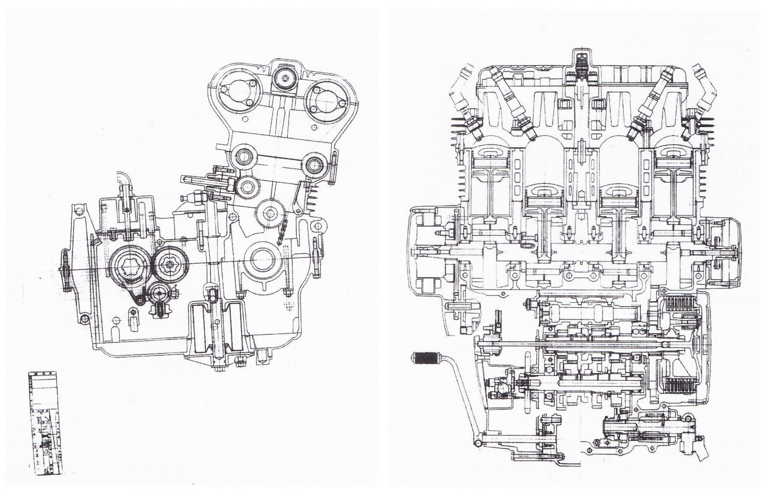
These drawings date from the production prototype to the early production phase.
The drive chain was a No. 630 and had a weaving mechanism for the chain.
However, we were able to quickly replace the No. 630 with a chain with a grease seal, eliminating the need for the weaving mechanism. - Damage to the tappet disc. This damage, unlike the damage that occurred on the N600, was caused by a change in the machining method of the tappet body. The cause of this was difficult to determine, so a device was built to apply impact pressure to the surfaces of the tappet and disc to test the strength of the disc. It was discovered that the crack had formed in the area where the tappet body met the grinding recess, which had been added to facilitate flatness. This made machining difficult, but we asked the manufacturer to machine it without the recess, and the problem was solved.
- Burned clutch disc. During very sudden acceleration, the clutch friction disc tends to burn. The method for determining clutch capacity was the same as for previous two-stroke engines, but it turned out that the four-stroke engine was more thermally demanding, so a very strict clutch testing standard was established. According to this standard, the diameter and number of clutch plates were increased to solve the problem. It is probably thanks to this that this model later became the basis for racing motorcycles and withstood displacement increases. 4)Air sucked into the oil pump. This was discovered during a rapid acceleration/deceleration test. The oil level fluctuates during rapid acceleration/deceleration, causing the intake area of the oil pump to come into contact with air and suck it in. This causes air to accumulate in the oil passage. In particular, the air remaining in the U-shaped section remained there even after the oil level returned to normal, preventing oil from entering the rear of the passage. To prevent this, a baffle plate (similar to a separator) was installed in the oil pan. A small opening was also installed on the non-discharge side of the oil pump to allow air to escape. This was possible because the crankshaft bearing system used a rolling bearing system. With a plain bearing system, it would have burned out much sooner than. In the final stages of setting the specifications for mass production, it was said that the finished motorcycle lacked a little driving stability. To improve stability, all modifications were made to the body, including an extension of the front fork and rear shock absorber, as well as a 20 mm extension of the swing arm to position the engine comparatively higher and further forward. This achieved good stability and handling despite the motorcycle's size. It also improved the durability of the drive chain. This was a minor countermeasure, as a small amount of engine oil was drained from the drive sprocket to improve lubrication. On the other hand, it caused the problem of oil splashes soiling the rider's clothing, so it wasn't a decisive solution.
This established the specifications for mass production. In June 1972, the editors-in-chief of the four major motorcycle magazines in the United States were invited to a presentation at the Kobe Trade Center Building in Japan, and preparations for the debut were complete.
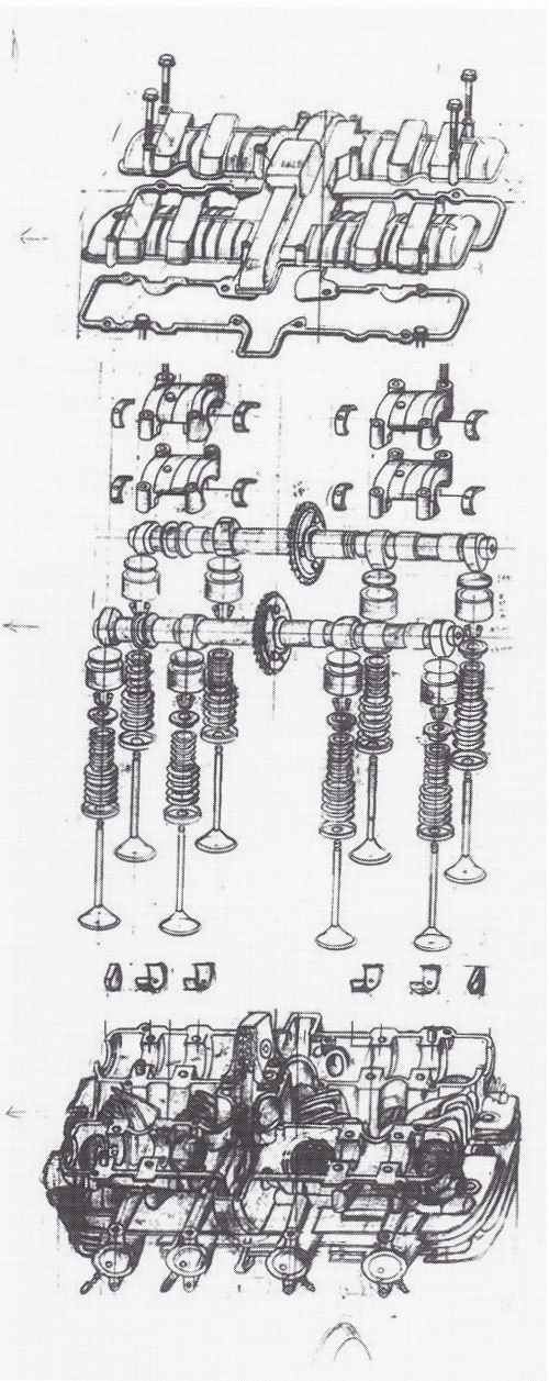
To ensure greater reliability, plain bearings are used for the camshaft.
In later models, the plain bearings were inspected and discarded.
The durability of the drive chain was also improved. This was a minor countermeasure, as a small amount of engine oil was drained from the drive sprocket to improve lubrication. On the other hand, this resulted in oil splashes that soiled the rider's clothing, so it wasn't a permanent solution.
Taking these measures into account, the specifications for mass production were established. In June 1972, the editors-in-chief of the four largest US motorcycle magazines were invited to Japan for a presentation at the Kobe Trade Center Building, and preparations for the debut were complete. Mass production for the American market began around August 1972. On the other hand, we wanted to release the same 903 cc specifications for the Japanese market. I received a report from Mr. Yamada, the department head: " Because we didn't want to provoke America, the four leading companies in the industry met and decided to limit the maximum displacement for the Japanese market to 750 cc " (I think this was around July 1972).
It would have been better for the manufacturers to just change the bore, but I felt that would have lost all of the power. So, to retain some of the Z1's power, we asked them to change the bore and stroke as well, and they agreed.
The main specifications of the Z2 are therefore 4 cylinders, DOHC, bore x stroke 64 mm x 58 mm, volume 746 cc. These bore x stroke dimensions are the same as those used on the N600. Using the same cylinder head as the 903 cc Z1 will affect intake and exhaust flow from and to the valve in the areas close to the head and cylinder, which is undesirable in terms of performance due to the so-called masking effect. Therefore, I thought that adding chamfers wouldn't have much of an impact on the bore and stroke up to 64 mm, so I changed the bore and stroke. The Z1 produced 82 hp at 8,500 rpm, the Z2 69 hp at 9,000 rpm, and the CB75O4 67 hp at 8,000 rpm. The power difference between the Z2 and the CB wasn't too great, but in practice, the difference in performance was significantly greater due to the better over-rev range.
I think the Z2 was more likely to be used as a racing engine than the CB due to its ease of maintenance and significant potential for performance improvements. Mass production of the Z2 began in February 1973 and got underway. Other changes included adjusting the venturi size of the Z2's carburetor from 28 mm to 26 mm. This change required a complete overhaul of the crankshaft system, and the mounting fixtures were also completely redesigned. This enabled the motorcycle to achieve the world's best performance in the 750 cc class at the time.
After series production began, there were complaints that the drive chain was stretching too quickly due to the high speed and power. The chain was equipped with an automatic oiling device, but this caused oil to splash and stain the rider's clothing. Therefore, grease was sealed between the chain pins and bushings, both ends were secured with O-rings, and the chain size was increased from #530 to #630, completely solving this problem.
The most important engine data of Z1 / Z2 is summarized below:
                                            Z1E                    Z2E
Inline cylinders
(Across the direction of travel)
Number of cylinders:                    cylinders: 4           cylinders: 4
Bore x Stroke:                           66mm x 66mm           64mm x 58mm
Displacement:                                8,5                   9,0
Maximum horse-power/rpm:                   82/8500               69/9000
Maximum torque kg-m/rpm:                   7,5/7000              5,9/7500
The Z1 and Z2 were each developed as a separate model, yet it was intended that there would be no difference between them. As for the intended use of the motorcycles, they are primarily used in the city. However, there are also many different uses for both models, from long-distance rides to extended tours in the USA to racing.
However, the Z models were not originally designed as all-purpose motorcycles, but rather for a specific purpose. This wide range of applications, however, also brought with it diverse requirements. Experienced riders who utilized this large displacement at full throttle had to be equipped with optional parts. For example, an oil cooler was required for endurance racing, so care was taken to ensure it could be easily installed from the outside. On the other hand, the loads in city traffic are only a few tenths of a second below full throttle, and riders who use the engine in this way place greater value on ride comfort and stability.
The Z1/Z2 engine is designed to be very maintenance-friendly compared to other manufacturers' engines. We therefore believe these models offer excellent durability characteristics not only for racing, but also for general riders. So, since it was Kawasaki's first four-cylinder, four-stroke motorcycle, we mass-produced it with a carefully engineered and tested mechanism to prevent failures. Therefore, I think there were some areas of excessive quality. However, I think this led to a sense of security and satisfaction with the product, and that's the reason for its 40 years of enthusiasm among people all over the world.

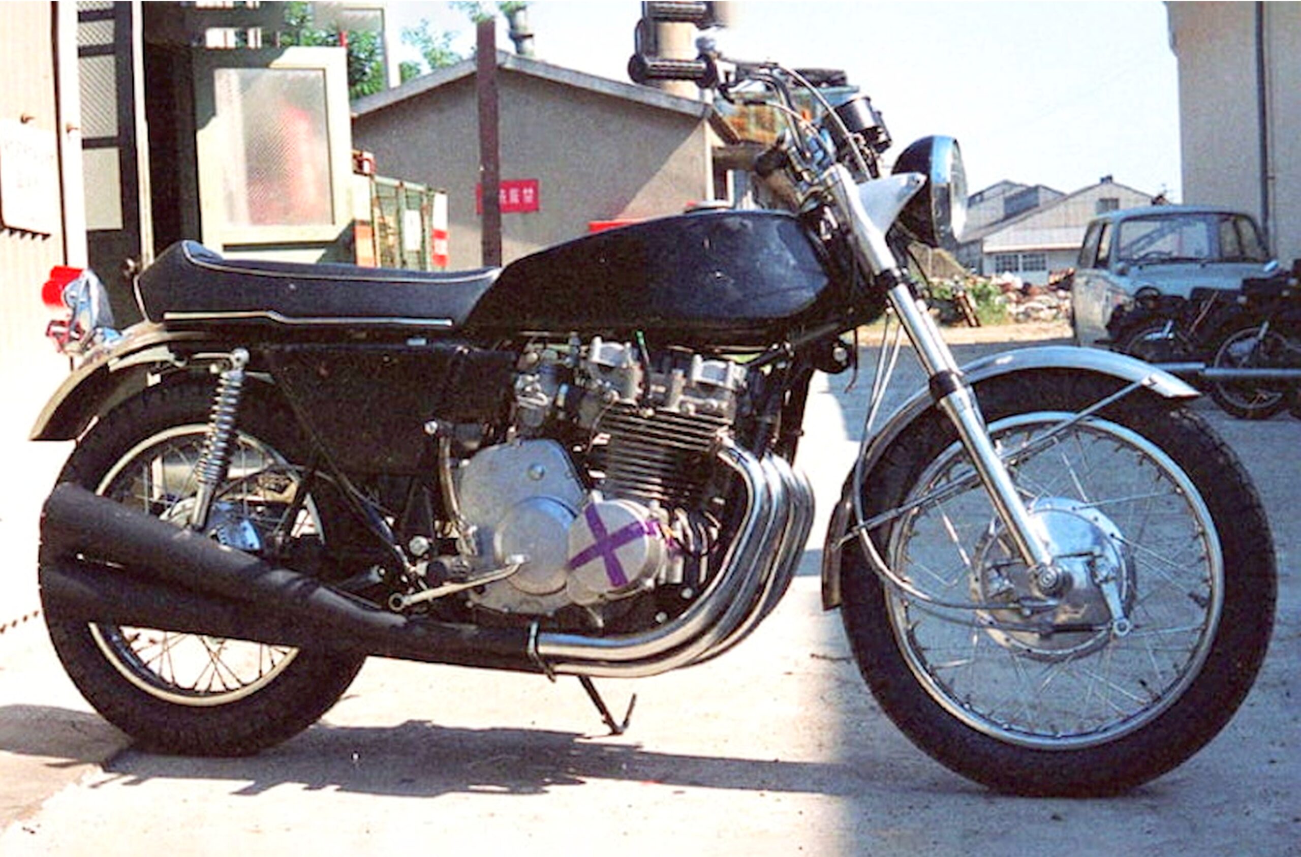
Prototypes T-103
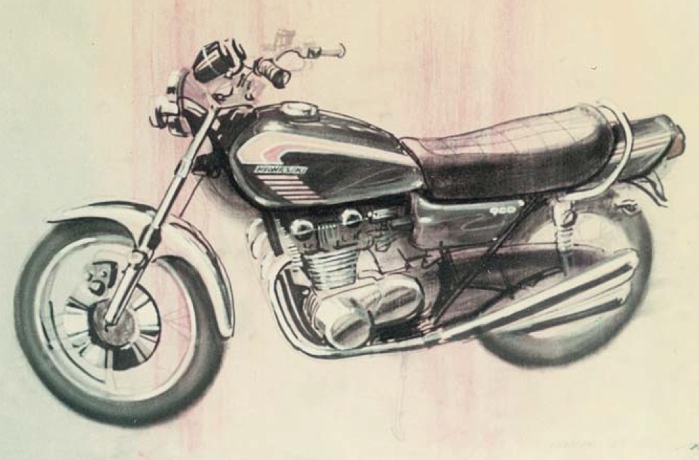
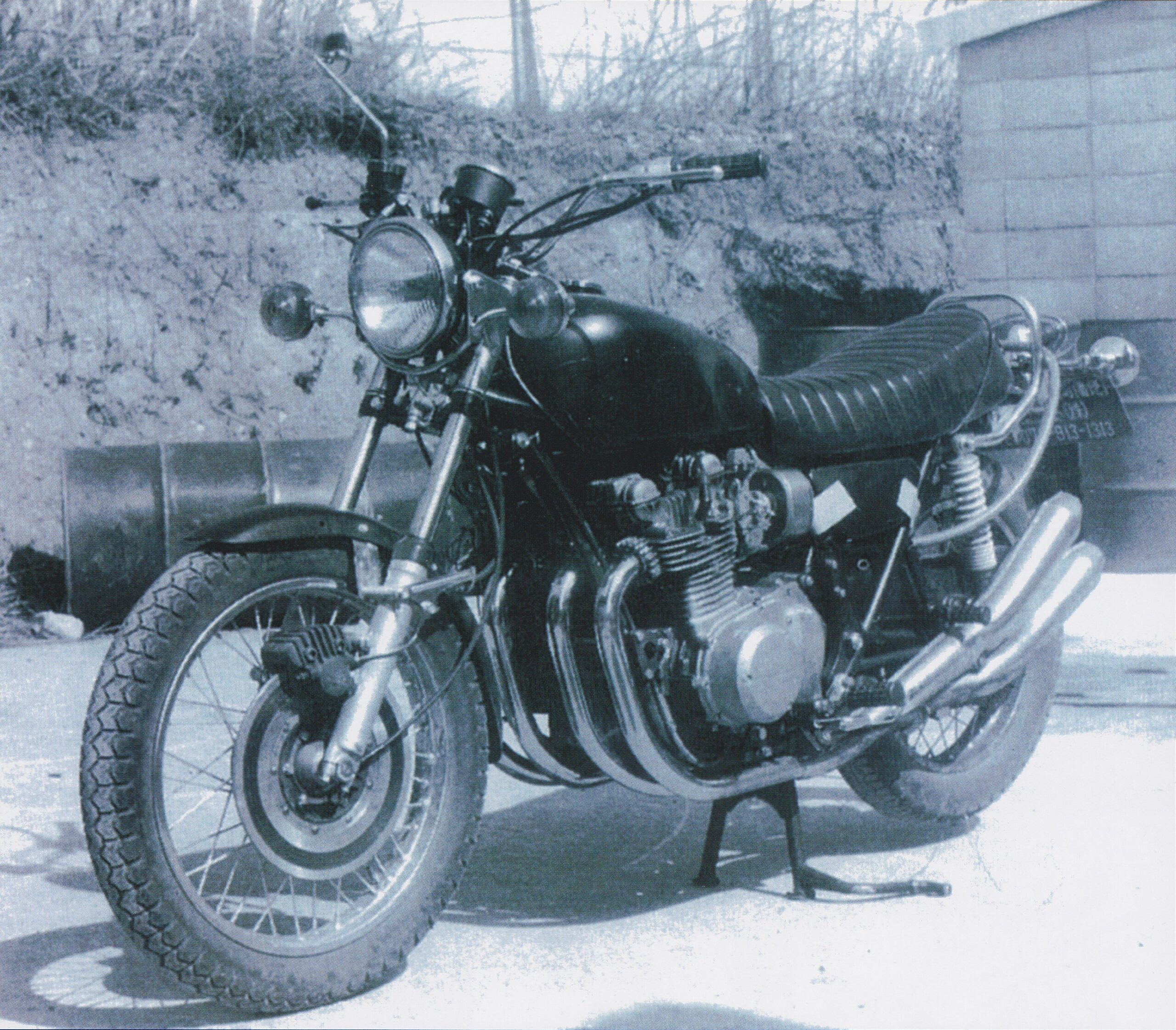
This was the first test model with a 900 cc engine, and seven were produced. According to the meeting documents of the time, it was named T-103, based on the body design of the 900 cc engine. The designer was not involved in the development at that time. As can be seen in the photo, the brakes, electrical system, and other parts were reused from other models. The tachometer pictured was a defective model, and there was no alternative at the time that could withstand the performance of the T-103. This model was built to fully exploit the potential of the frame and the specifications of the functional parts. The frame structure is an important factor in the car's style, but we were confident that it could be adopted unchanged during this phase. Design work began based on this model. The body design also met its purpose based on the test results of this model, and we decided to proceed to the next design phase for mass production. Furthermore, the speed test proved that this model could reach a speed of 230 km/h. The T-103 model in the photo is one of the prototypes that were hastily completed in preparation for overseas testing in the USA.
Most of the body design parts were in production, so the six major regular design parts (rearview mirror, complete gauge cluster, front fender, seat, side cover, tail section, etc.) had not yet been finalized. Temporary parts were used in this model, with the exception of the muffler. Since the fuel tank is a large mold, this is a temporary mold, but it almost completely achieved the designed shape. These parts are very close to the final design (before the rough mold was polished). However, the DOHC markings were not engraved on this temporary mold. I believe the model was sent to America in this condition. The engine and frame were already completed. Since the design work (creating the final mold, which was urgent) began with the engine's outer skin as a priority, the body panels weren't completed in time, so they had to make do with temporary parts. This is the prototype that formed the basis of the Z-1 (by Norimasa Tada).
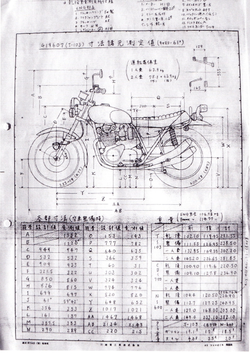
The T-103 line drawing of this body by Togashi Toshio
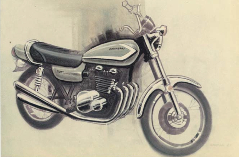
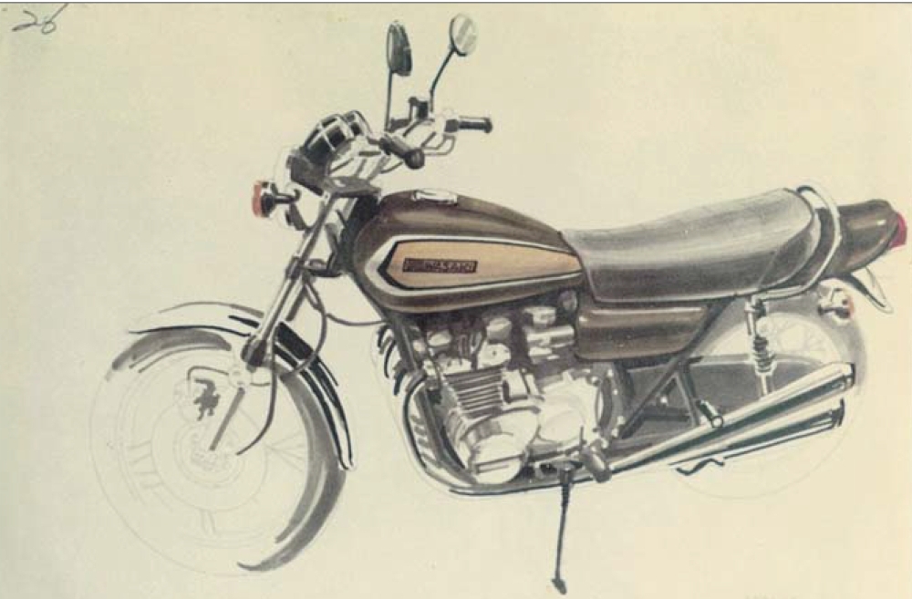
Z-1 Color and Graphic Design (by Norimasa Tada)
The three images presented here are perspective views (three-dimensional see-through images) created for color and graphic purposes. The images (top) and (middle) are similar graphic designs, differing only in the presence or absence of color. The goal was to make the fuel tank as small and compact as possible. The center image, in particular, shows a series of side graphics inspired by the Mach series. The image below shows a tank graphic aimed at overall balance, with the number "900" added to the side.
Some of these designs were unsatisfactory in my personal evaluation and were all rejected without internal review. The final sketch of the tank design ultimately adopted for the Z-1 is not included, but it is a draft by the design team at the time: myself, Toru Yamauchi, and the late Tadahiro Kurishima (Tada Norimasa).
Tada Norimasa
Z-1 Color and Graphic : top
Z-1 Color and Graphic : middle
Z-1 Color and Graphic : bottom